
Description
Synchronous rectification technology introduction:
Synchronous rectification is a new technology that uses special power MOSFETs with extremely low on-state resistance to replace rectifier diodes to reduce rectification losses. It can greatly improve the efficiency of the DC/DC converter and there is no dead-time voltage caused by the Schottky barrier voltage. Power MOSFET is a voltage-controlled device, and its volt-ampere characteristics are linear when it is turned on. When using a power MOSFET as a rectifier, the gate voltage must be synchronized with the phase of the rectified voltage to complete the rectification function, so it is called synchronous rectification. Synchronous rectification technology greatly reduces the rectification loss at the output end of the switching power supply, thereby improving the conversion efficiency and reducing the heat of the power supply itself.
Parameter Description:
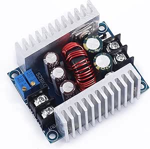
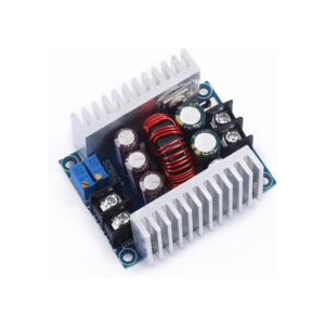
Module properties: synchronous rectification, non-isolated buck, constant current and constant voltage module, CC CV charging module
Scope of application: high-power LED constant current drive, lithium battery charging (including ferroelectric), 4V, 6V, 12V, 14V, 24V battery charging, NiCd NiMH battery (battery pack) charging, solar panels, wind turbines
Input voltage: DC6-40V
Output voltage: continuously adjustable (1.2-35VDC) for a long time below 32V (suitable for applications where the input voltage is higher than the output voltage and cannot be boosted)
Output current: maximum 20A within 15A for a long time (please add a fan for heat dissipation if the temperature of the power tube exceeds 65 degrees, and use derating for high voltage output)
Current limiting range: 0.2-20A (adjustment) If the module exceeds 65 degrees, please add a fan.
Minimum dropout voltage: 3V
Working frequency: 150KHZ
Conversion efficiency: up to about 96% The efficiency is related to the pressure difference and the use environment
Output ripple: about 50mV ripple (no noise) 20M bandwidth (for reference only) input 24V measured
Operating temperature: -10℃ to +75℃) (Please pay attention to the temperature of the power tube in actual use, if the temperature is too high, please strengthen the heat dissipation or derate the use)
Potentiometer adjustment direction: clockwise (increase), counterclockwise (decrease)
Output short-circuit protection: yes (instantaneous protection) constant current (currently set constant current value cannot be short-circuited for a long time)
Input reverse polarity protection: none,
Output anti-backflow: none, for self-charged or inductive loads, an external 2-pole tube is required!
Wiring method: terminal block
Module size: 60*53*30MM
Net weight: about 85 grams
Output current adjustment method:
1. Adjust the CV potentiometer and set the output voltage to the voltage value you need according to your load requirements.
2. Set the CC potentiometer counterclockwise for about 30 turns (that is, set the output current to the minimum), connect the LED, and adjust the CC potentiometer to the current you need. For battery charging, after the battery is fully discharged, connect to the output and adjust the CC to the current you need. The more, the smaller the charging current.)
Wiring Instructions:
OUT+: output positive
OUT-: output negative
+IN: input positive
-IN: Enter a negative number
CV: Output Voltage Regulation
CC: output current regulation
EN: Enable, low level closes output; Pause, high voltage level active
When the input and output are grounded, no-load CV output constant voltage, CC output constant current
Reviews
There are no reviews yet.